The Microsoft Foundation Class (MFC) library provides a set of functions, constants, data types, and classes to simplify creating applications for the Microsoft Windows operating systems. In this tutorial, you will learn all about how to start and create windows based applications using MFC.
We have assumed that you know the following −
The Microsoft Foundation Class Library (MFC) is an "application framework" for programming in Microsoft Windows. MFC provides much of the code, which are required for the following −
You can easily extend or override the basic functionality the MFC framework in you C++ applications by adding your application-specific code into MFC framework.
The MFC framework is a powerful approach that lets you build upon the work of expert programmers for Windows. MFC framework has the following advantages.
Microsoft Visual C++ is a programming environment used to create applications for the Microsoft Windows operating systems. To use MFC framework in your C++ application, you must have installed either Microsoft Visual C++ or Microsoft Visual Studio. Microsoft Visual Studio also contains the Microsoft Visual C++ environment.
Microsoft provides a free version of visual studio which also contains SQL Server and it can be downloaded from https://www.visualstudio.com/en-us/downloads/downloadvisual- studio-vs.aspx.
Following are the installation steps.
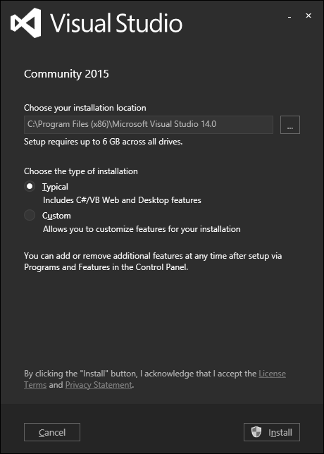
Step 1 − Once Visual Studio is downloaded, run the installer. The following dialog box will be displayed.
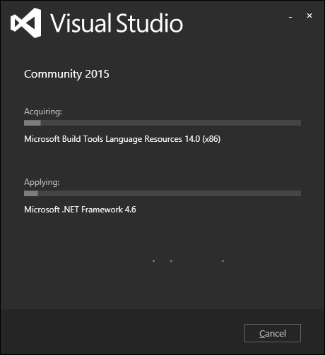
Step 2 − Click Install to start the installation process.
Step 3 − Once Visual Studio is installed successfully, you will see the following dialog box.
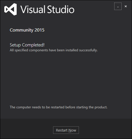
Step 4 − Close this dialog box and restart your computer if required.
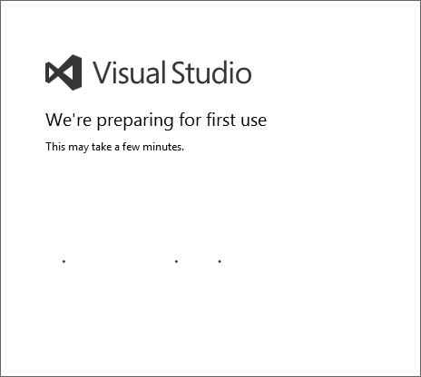
Step 5 − Open Visual studio from the Start menu, which will open the following dialog box. It will take some time for preparation, while starting for the first time.
Step 6 − Next, you will see the main window of Visual Studio.
Step 7 − You are now ready to start your application.
In this chapter, we will be covering the different types of VC++ projects. Visual Studio includes several kinds of Visual C++ project templates. These templates help to create the basic program structure, menus, toolbars, icons, references, and include statements that are appropriate for the kind of project you want to create. Following are some of the salient features of the templates.
In MFC, you can use the following project templates.
MFC Application
An MFC application is an executable application for Windows that is based on the Microsoft Foundation Class (MFC) Library. The easiest way to create an MFC application is to use the MFC Application Wizard.
MFC ActiveX Control
ActiveX control programs are modular programs designed to give a specific type of functionality to a parent application. For example, you can create a control such as a button for use in a dialog, or toolbar or on a Web page.
An MFC DLL is a binary file that acts as a shared library of functions that can be used simultaneously by multiple applications. The easiest way to create an MFC DLL project is to use the MFC DLL Wizard.
Following are some General templates which can also be used to create MFC application −
Empty Project
Projects are the logical containers for everything that's needed to build your application. You can then add more new or existing projects to the solution if necessary.
Custom Wizard
The Visual C++ Custom Wizard is the tool to use when you need to create a new custom wizard. The easiest way to create a custom wizard is to use the Custom Wizard.
In this chapter, we will look at a working MFC example. To create an MFC application, you can use wizards to customize your projects. You can also create an application from scratch.
Following are the steps to create a project using project templates available in Visual Studio.
Step 1 − Open the Visual studio and click on the File → New → Project menu option.
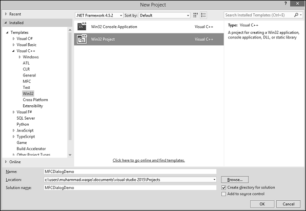
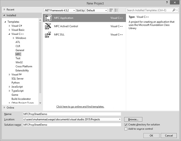
Step 2 − You can now see that the New Project dialog box is open.
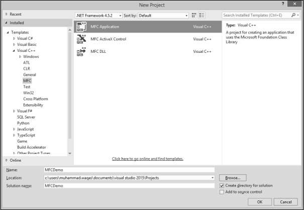
Step 3 − From the left pane, select Templates → Visual C++ → MFC
Step 4 − In the middle pane, select MFC Application.
Step 5 − Enter the project name ‘MFCDemo’ in the Name field and click OK to continue. You will see the following dialog.
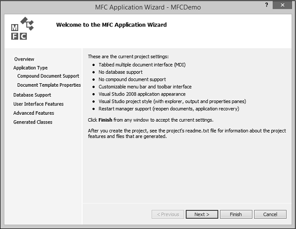
Step 6 − Click Next.
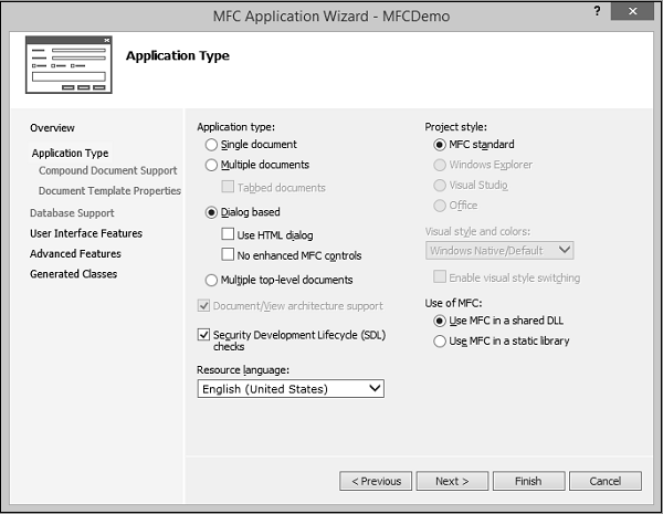
Step 7 − Select the options which are shown in the dialog box given above and click Next.
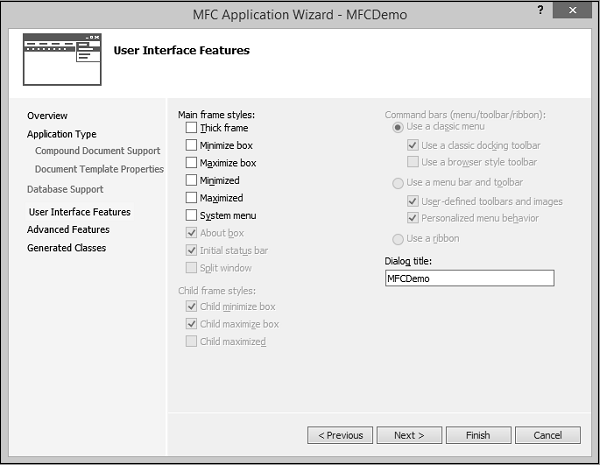
Step 8 − Uncheck all options and click Finish button.
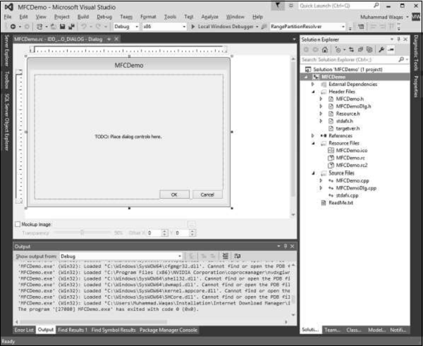
You can now see that the MFC wizard creates this Dialog Box and the project files by default.
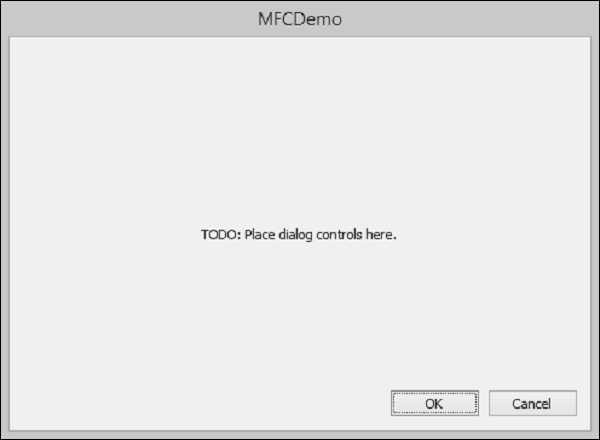
Step 9 − Run this application, you will see the following output.
You can also create an MFC application from scratch. To create an MFC application, you need to follow the following Steps.
Step 1 − Open the Visual studio and click on the File → New → Project menu option.
Step 2 − You can now see the New Project dialog box.
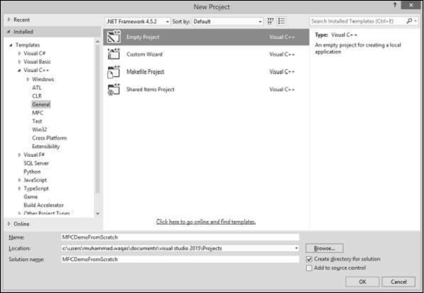
Step 3 − From the left pane, select Templates → Visual C++ → General.
Step 4 − In the middle pane, select Empty
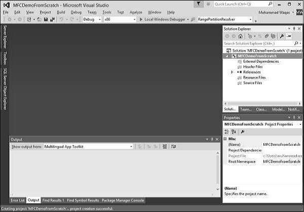
Step 5 − Enter project name ‘MFCDemoFromScratch’ in the Name field and click OK to continue. You will see that an empty project is created.
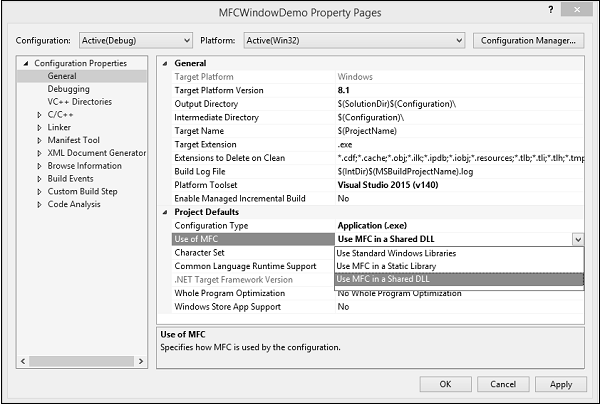
Step 6 − To make it an MFC project, right-click on the project and select Properties.
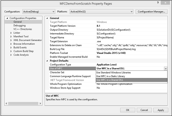
Step 7 − In the left section, click Configuration Properties → General.
Step 8 − Select the Use MFC in Shared DLL option in Project Defaults section and click OK.
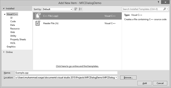
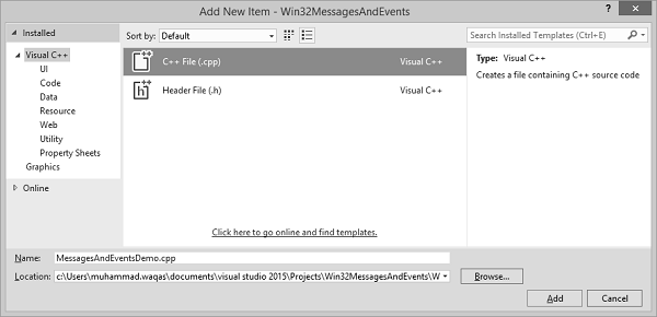
Step 9 − As it is an empty project now; we need to add a C++ file. So, right-click on the project and select Add → New Item…
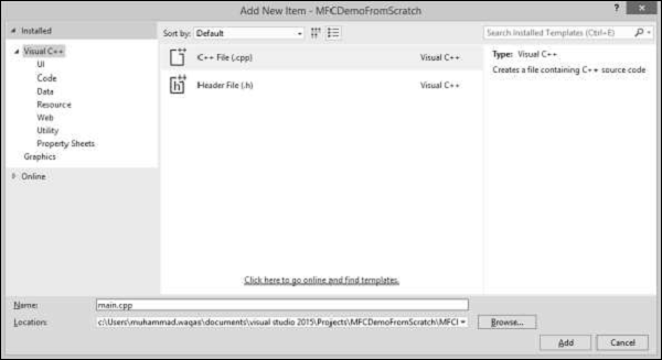
Step 10 − Select C++ File (.cpp) in the middle pane and enter file name in the Name field and click Add button.
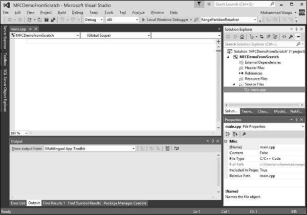
Step 11 − You can now see the main.cpp file added under the Source Files folder.
Step 12 − Let us add the following code in this file.
#include using namespace std; void main()Step 13 − When you run this application, you will see the following output on console.
*************************************** MFC Application Tutorial ***************************************
In this chapter, we will be covering the fundamentals of Windows. To create a program, also called an application, you derive a class from the MFC's CWinApp. CWinApp stands for Class for a Windows Application.
Let us look into a simple example by creating a new Win32 project.
Step 1 − Open the Visual studio and click on the File → New → Project menu option.
Step 2 − You can now see the New Project dialog box.
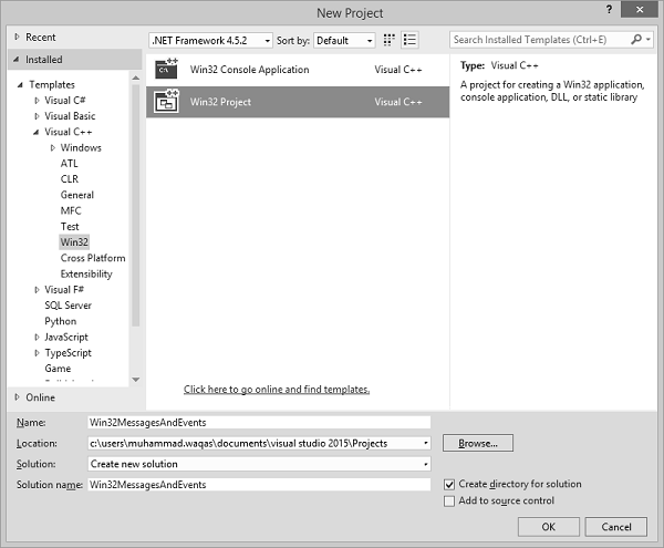
Step 3 − From the left pane, select Templates → Visual C++ → Win32.
Step 4 − In the middle pane, select Win32 Project.
Step 5 − Enter the project name ‘MFCWindowDemo’ in the Name field and click OK to continue. You will see the following dialog box.
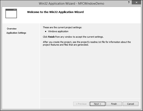
Step 6 − Click Next.
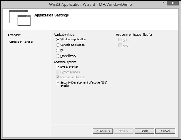
Step 7 − Select the options as shown in the dialog box given above and click Finish.
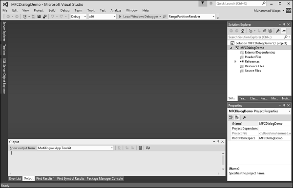
Step 8 − An empty project is created.
Step 9 − To make it an MFC project, right-click on the project and select Properties.
Step 10 − In the left section, click Configuration Properties → General.
Step 11 − Select the Use MFC in Shared DLL option in Project Defaults section and click OK.
Step 12 − Add a new source file.
Step 13 − Right-click on your Project and select Add → New Item.
Step 14 − In the Templates section, click C++ File (.cpp).
Step 15 − Set the Name as Example and click Add.
Any application has two main sections −
Let us create a window using the following steps −
Step 1 − To create an application, we need to derive a class from the MFC's CWinApp.
#include class CExample : public CWinApp < BOOL InitInstance() < return TRUE; >>;
Step 2 − We also need a frame/window to show the content of our application.
Step 3 − For this, we need to add another class and derive it from the MFC's CFrameWnd class and implement its constructor and a call the Create() method, which will create a frame/window as shown in the following code.
class CMyFrame : public CFrameWnd < public: CMyFrame() < Create(NULL, _T("MFC Application Tutorial")); >>;
Step 4 − As you can see that Create() method needs two parameters, the name of the class, which should be passed as NULL, and the name of the window, which is the string that will be shown on the title bar.
After creating a window, to let the application use it, you can use a pointer to show the class used to create the window. In this case, the pointer would be CFrameWnd. To use the frame window, assign its pointer to the CWinThread::m_pMainWnd member variable. This is done in the InitInstance() implementation of your application.
Step 1 − Here is the implementation of InitInstance() in CExample class.
class CExample : public CWinApp < BOOL InitInstance() < CMyFrame *Frame = new CMyFrame(); m_pMainWnd = Frame; Frame->ShowWindow(SW_NORMAL); Frame->UpdateWindow(); return TRUE; > >;
Step 2 − Following is the complete implementation of Example.cpp file.
#include class CMyFrame : public CFrameWnd < public: CMyFrame() < Create(NULL, _T("MFC Application Tutorial")); >>; class CExample : public CWinApp < BOOL InitInstance() < CMyFrame *Frame = new CMyFrame(); m_pMainWnd = Frame; Frame->ShowWindow(SW_NORMAL); Frame->UpdateWindow(); return TRUE; > >; CExample theApp;
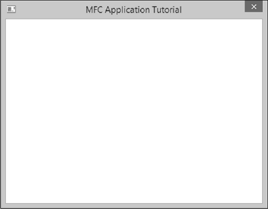
Step 3 − When we run the above application, the following window is created.
Windows styles are characteristics that control features such as window appearance, borders, minimized or maximized state, or other resizing states, etc.
Following is a list of styles which you can use while creating a Window.
Creates a window that has a border.
Creates a window that has a title bar (implies the WS_BORDER style). Cannot be used with the WS_DLGFRAME style.
Creates a child window. Cannot be used with the WS_POPUP style.
WS_CHILDWINDOW
Same as the WS_CHILD style.
WS_CLIPCHILDREN
Excludes the area occupied by child windows when you draw within the parent window. Used when you create the parent window.
WS_CLIPSIBLINGS
Clips child windows relative to each other; that is, when a particular child window receives a paint message, the WS_CLIPSIBLINGS style clips all other overlapped child windows out of the region of the child window to be updated. (If WS_CLIPSIBLINGS is not given and child windows overlap, when you draw within the client area of a child window, it is possible to draw within the client area of a neighboring child window.) For use with the WS_CHILD style only.
WS_DISABLED
Creates a window that is initially disabled.
WS_DLGFRAME
Creates a window with a double border but no title.
Specifies the first control of a group of controls in which the user can move from one control to the next with the arrow keys. All controls defined with the WS_GROUP style FALSE after the first control belong to the same group. The next control with the WS_GROUP style starts the next group (that is, one group ends where the next begins).
Creates a window that has a horizontal scroll bar.
Creates a window that is initially minimized. Same as the WS_MINIMIZE style.
WS_MAXIMIZE
Creates a window of maximum size.
WS_MAXIMIZEBOX
Creates a window that has a Maximize button.
WS_MINIMIZE
Creates a window that is initially minimized. For use with the WS_OVERLAPPED style only.
WS_MINIMIZEBOX
Creates a window that has a Minimize button.
WS_OVERLAPPED
Creates an overlapped window. An overlapped window usually has a caption and a border.
WS_OVERLAPPED WINDOW
Creates an overlapped window with the WS_OVERLAPPED, WS_CAPTION, WS_SYSMENU, WS_THICKFRAME, WS_MINIMIZEBOX, and WS_MAXIMIZEBOX styles.
Creates a pop-up window. Cannot be used with the WS_CHILD style.
WS_POPUPWINDOW
Creates a pop-up window with the WS_BORDER, WS_POPUP, and WS_SYSMENU styles. The WS_CAPTION style must be combined with the WS_POPUPWINDOW style to make the Control menu visible.
Creates a window that has a sizing border. Same as the WS_THICKFRAME style.
Creates a window that has a Control-menu box in its title bar. Used only for windows with title bars.
Specifies one of any number of controls through which the user can move by using the TAB key. The TAB key moves the user to the next control specified by the WS_TABSTOP style.
WS_THICKFRAME
Creates a window with a thick frame that can be used to size the window.
Creates an overlapped window. An overlapped window has a title bar and a border. Same as the WS_OVERLAPPED style.
WS_TILEDWINDOW
Creates an overlapped window with the WS_OVERLAPPED, WS_CAPTION, WS_SYSMENU, WS_THICKFRAME, WS_MINIMIZEBOX, and WS_MAXIMIZEBOX styles. Same as the WS_OVERLAPPEDWINDOW style.
Creates a window that is initially visible.
Creates a window that has a vertical scroll bar.
Step 1 − Let us look into a simple example in which we will add some styling. After creating a window, to display it to the user, we can apply the WS_VISIBLE style to it and additionally, we will also add WS_OVERLAPPED style. Here is an implementation −
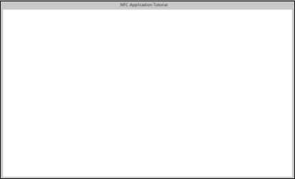
class CMyFrame : public CFrameWnd < public: CMyFrame() < Create(NULL, _T("MFC Application Tutorial"), WS_VISIBLE | WS_OVERLAPPED); >>;
Step 2 − When you run this application, the following window is created.
You can now see that the minimize, maximize, and close options do not appear anymore.
To locate things displayed on the monitor, the computer uses a coordinate system similar to the Cartesian's, but the origin is located on the top left corner of the screen. Using this coordinate system, any point can be located by its distance from the top left corner of the screen of the horizontal and the vertical axes.
The Win32 library provides a structure called POINT defined as follows −
typedef struct tagPOINT < LONG x; LONG y; >POINT;
CPoint(); CPoint(int X, int Y);
While a point is used to locate an object on the screen, each window has a size. The size provides two measures related to an object.
The Win32 library uses the SIZE structure defined as follows −
typedef struct tagSIZE < int cx; int cy; >SIZE;
Besides the Win32's SIZE structure, the MFC provides the CSize class. This class has the same functionality as SIZE but adds features of a C++ class. It provides five constructors that allow you to create a size variable in any way of your choice.
CSize(); CSize(int initCX, int initCY); CSize(SIZE initSize); CSize(POINT initPt); CSize(DWORD dwSize);
When a Window displays, it can be identified on the screen by its location with regards to the borders of the monitor. A Window can also be identified by its width and height. These characteristics are specified or controlled by the rect argument of the Create() method. This argument is a rectangle that can be created through the Win32 RECT structure.
typedef struct _RECT < LONG left; LONG top; LONG right; LONG bottom; >RECT, *PRECT;
Besides the Win32's RECT structure, the MFC provides the CRect class which has the following constructors −
CRect(); CRect(int l, int t, int r, int b); CRect(const RECT& srcRect); CRect(LPCRECT lpSrcRect); CRect(POINT point, SIZE size); CRect(POINT topLeft, POINT bottomRight);
Let us look into a simple example in which we will specify the location and the size of the window
class CMyFrame : public CFrameWnd < public: CMyFrame() < Create(NULL, _T("MFC Application Tutorial"), WS_SYSMENU, CRect(90, 120, 550, 480)); >>;
When you run this application, the following window is created on the top left corner of your screen as specified in CRect constructor in the first two parameters. The last two parameters are the size of the Window.
In the real world, many applications are made of different Windows. When an application uses various Windows, most of the objects depend on a particular one. It could be the first Window that was created or another window that you designated. Such a Window is referred to as the Parent Window. All the other windows depend on it directly or indirectly.
Let us look into an example which has only one Window, and there is no parent Window available, so we will pass the argument with NULL value as shown in the following code −
class CMyFrame : public CFrameWnd < public: CMyFrame() < Create(NULL, _T("MFC Application Tutorial"), WS_SYSMENU, CRect(90, 120, 550, 480), NULL); >>;
When you run the above application, you see the same output.
In this chapter, we will be covering the Dialog boxes. Applications for Windows frequently communicate with the user through dialog boxes. CDialog class provides an interface for managing dialog boxes. The Visual C++ dialog editor makes it easy to design dialog boxes and create their dialog-template resources.
Let us look into a simple example by creating a new Win32 project.
Step 1 − Open the Visual studio and click on the File → New → Project menu option.
Step 2 − You can now see the New Project dialog box.
Step 3 − From the left pane, select Templates → Visual C++ → Win32.
Step 4 − In the middle pane, select Win32 Project.
Step 5 − Enter project name ‘MFCDialogDemo’ in the Name field and click OK to continue. You will see the following dialog.
Step 6 − Click Next.
Step 7 − Select the options shown in the dialog box given above and click Finish.
Step 8 − An empty project is created.
Step 9 − To make it a MFC project, right-click on the project and select Properties.
Step 10 − In the left section, click Configuration Properties → General.
Step 11 − Select the Use MFC in Shared DLL option in Project Defaults section and click OK.
Step 12 − Add a new source file.
Step 13 − Right-click on your Project and select Add → New Item.
Step 14 − In the Templates section, click C++ File (.cpp)
Step 15 − Set the Name as Example and click Add.
Step 16 − To create an application, we need to add a class and derive it from the MFC's CWinApp.
#include class CExample : public CWinApp < public: BOOL InitInstance(); >;
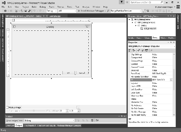
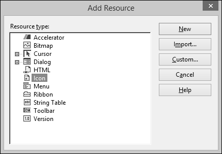
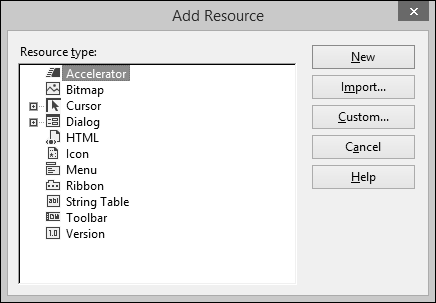
Step 1 − To create a dialog box, right-click on the Resource Files folder in solution explorer and select Add → Resource.
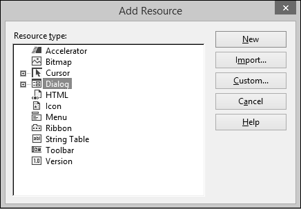
Step 2 − In the Add Resource dialog box, select Dialog and click New.
Step 3 − A dialog box requires some preparation before actually programmatically creating it.
Step 4 − A dialog box can first be manually created as a text file (in a resource file).
Step 5 − You can now see the MFCDialogDemo.rc file created under Resource Files.
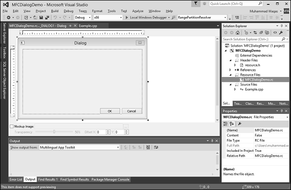
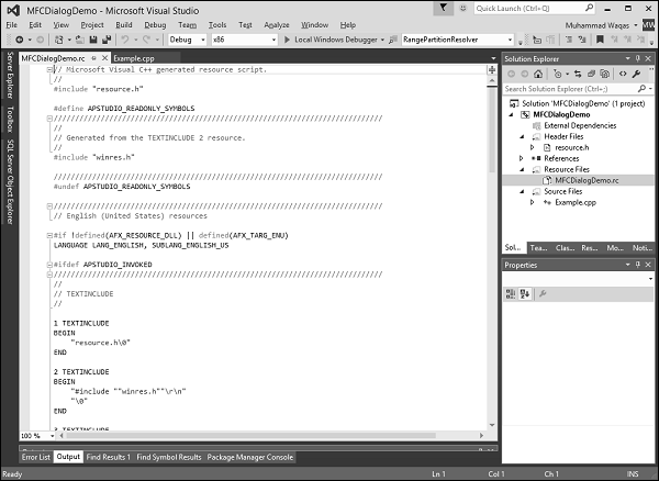
Step 6 − The resource file is open in designer. The same can be opened as a text file. Rightclick on the resource file and select Open With.
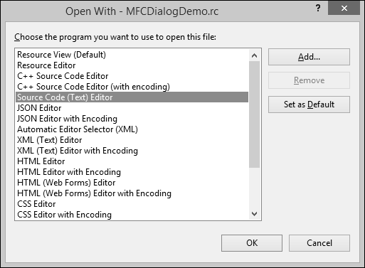
Step 7 − Select the Source Code (Text) editor and click Add button.
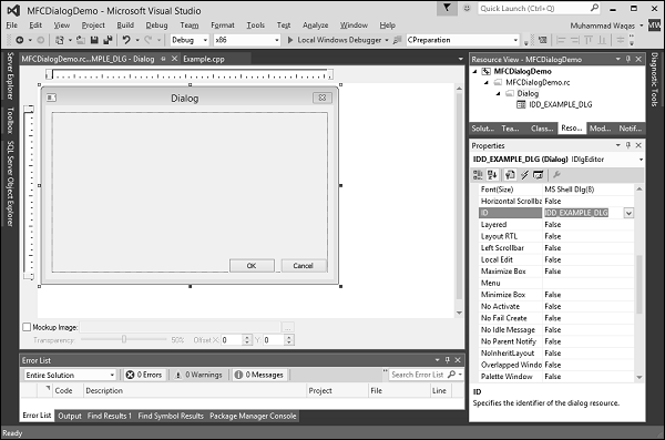
Step 8 − Go back to the designer and right-click on the dialog and select Properties.
Step 9 − You need to choose out of the many options.
Step 10 − Like most other controls, a dialog box must be identified. The identifier (ID) of a dialog box usually starts with IDD_, Let us change the ID to IDD_EXAMPLE_DLG.
A dialog box must be “physically” located on an application. Because a dialog box is usually created as a parent to other controls, its location depends on its relationship to its parent window or to the desktop.
If you look and the Properties window, you see two fields, X Pos and Y Pos.
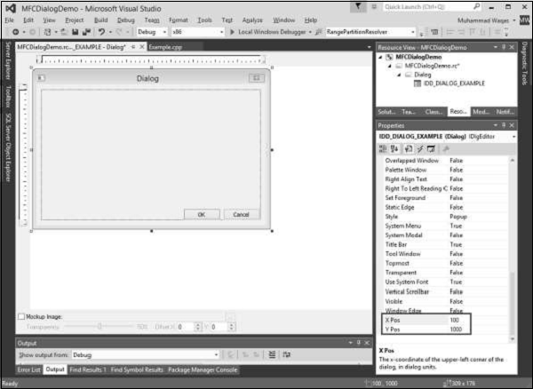
By default, these fields are set to zero. You can also change as shown above.
If you specify these two dimensions as 0, the left and top borders of the dialog box would be set so the object appears in the center-middle of the screen.
The dimensions of a dialog box refer to its width and its height. You can resize the width and height with the help of mouse in designer window.
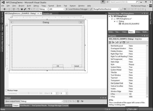
You can see the changes in width and height on the Status Bar.
The base class used for displaying dialog boxes on the screen is CDialog class. To create a dialog box, we need to derive a class from CDialog. The CDialog class itself provides three constructors which are as follows −
CDialog(); CDialog(UINT nIDTemplate, CWnd* pParentWnd = NULL); CDialog(LPCTSTR lpszTemplateName, CWnd* pParentWnd = NULL);
Let us create another class CExampleDlg and derive it from CDialog. We will implement its default constructor destructor as shown in the following code.
class CExampleDlg : public CDialog < public: enum < IDD = IDD_EXAMPLE_DLG >; CExampleDlg(); ~CExampleDlg(); >; CExampleDlg::CExampleDlg():CDialog(CExampleDlg::IDD) < >CExampleDlg::~CExampleDlg()We need to instantiate this dialog on CExample::InitInstance() method as shown in the following code.
BOOL CExample::InitInstance()There are two types of dialog boxes − modeless and modal. Modal and modeless dialog boxes differ by the process used to create and display them.
Step 1 − To display the dialog box as modal, in the CExample::InitInstance() event call the DoModal() method using your dialog variable −
BOOL CExample::InitInstance()Step 2 − Here is the complete implementation of Example.cpp file.
#include #include "resource.h" class CExample : public CWinApp < public: BOOL InitInstance(); >; class CExampleDlg : public CDialog < public: enum < IDD = IDD_EXAMPLE_DLG >; CExampleDlg(); ~CExampleDlg(); >; CExampleDlg::CExampleDlg():CDialog(CExampleDlg::IDD) < >CExampleDlg::~CExampleDlg() < >BOOL CExample::InitInstance() < CExampleDlg myDlg; m_pMainWnd = &myDlg; myDlg.DoModal(); return TRUE; >CExample MyApp;
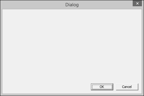
Step 3 − When the above code is compiled and executed, you will see the following dialog box.
Microsoft Visual Studio provides an easier way to create an application that is mainly based on a dialog box. Here are the steps to create a dialog base project using project templates available in Visual Studio −
Step 1 − Open the Visual studio and click on the File → New → Project menu option. You can see the New Project dialog box.

Step 2 − From the left pane, select Templates → Visual C++ → MFC.
Step 3 − In the middle pane, select MFC Application.
Step 4 − Enter project name ‘MFCModalDemo’ in the Name field and click OK to continue. You will see the following dialog box.
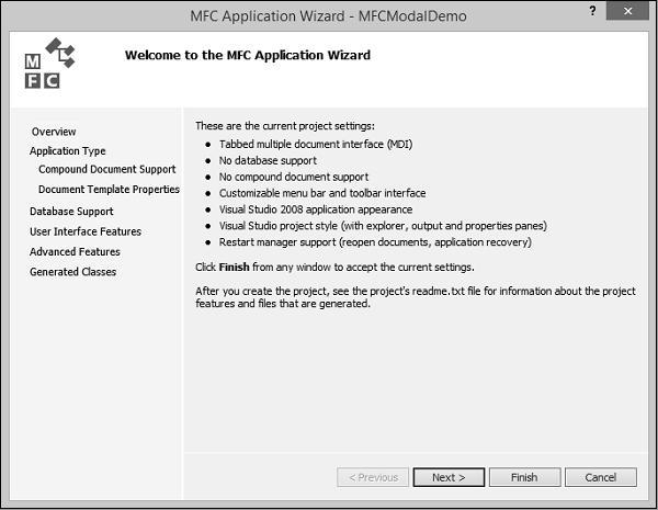
Step 5 − Click Next.

Step 6 − Select the options shown in the above dialog box and click Next.
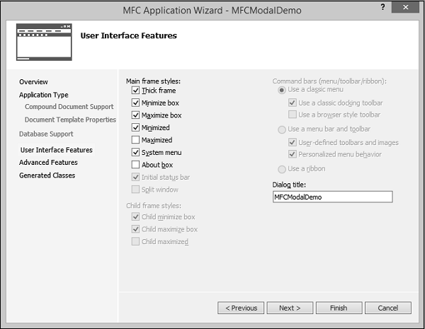
Step 7 − Check all the options that you choose to have on your dialog box like Maximize and Minimize Boxes and click Next.
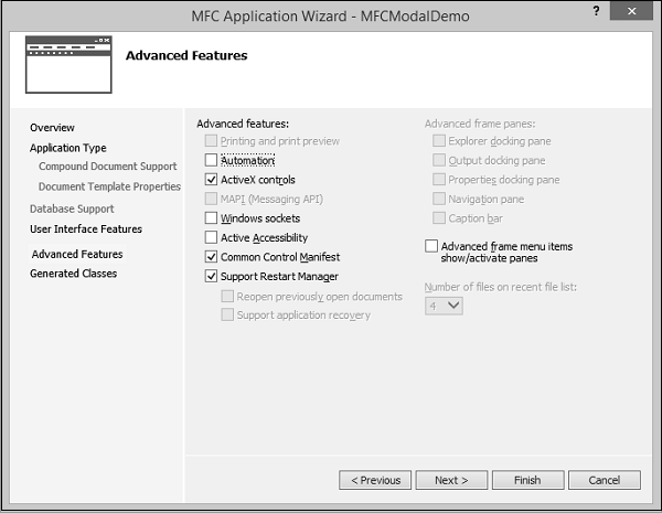
Step 8 − Click Next.
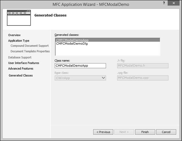
Step 9 − It will generate these two classes. You can change the name of the classes and click Finish.
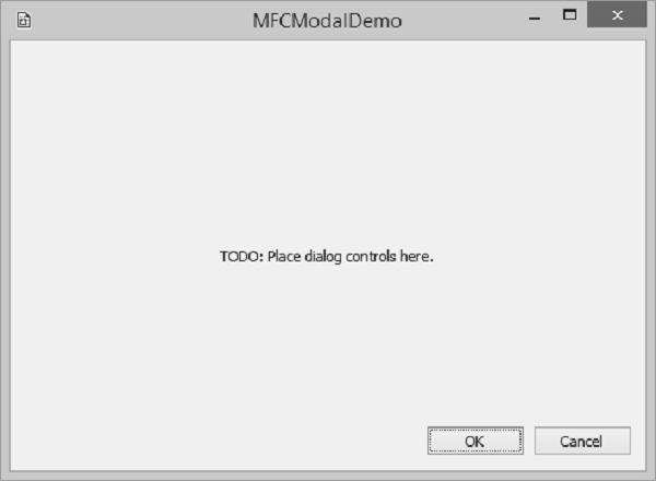
Step 10 − You can now see that the MFC wizard creates this Dialog Box and the project files by default.
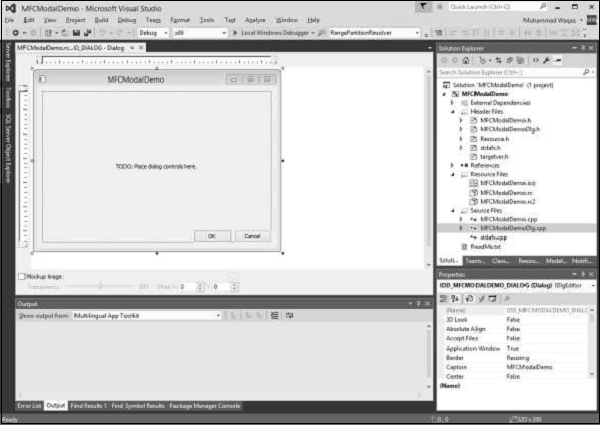
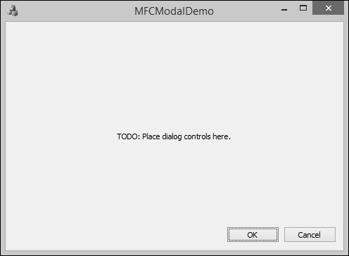
Step 11 − When you run this application, you will see the following output.
A resource is a text file that allows the compiler to manage objects such as pictures, sounds, mouse cursors, dialog boxes, etc. Microsoft Visual Studio makes creating a resource file particularly easy by providing the necessary tools in the same environment used to program. This means, you usually do not have to use an external application to create or configure a resource file. Following are some important features related to resources.
An identifier is a symbol which is a constant integer whose name usually starts with ID. It consists of two parts − a text string (symbol name) mapped to an integer value (symbol value).
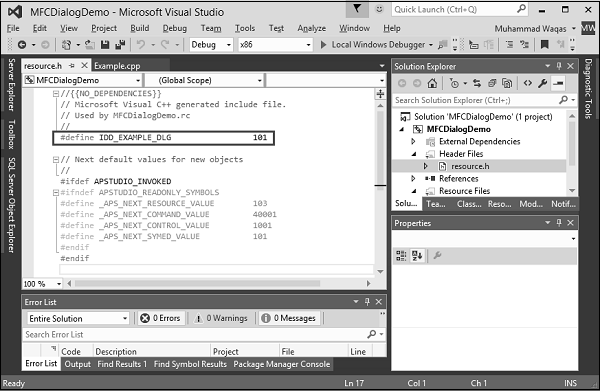
Step 1 − Let us look into our CMFCDialogDemo example from the last chapter in which we have created a dialog box and its ID is IDD_EXAMPLE_DLG.
Step 2 − Go to the Solution Explorer, you will see the resource.h file under Header Files. Continue by opening this file in editor and you will see the dialog box identifier and its integer value as well.
An icon is a small picture used on a window which represents an application. It is used in two main scenarios.
If you look at our MFCModalDemo example, you will see that Visual studio was using a default icon for the title bar as shown in the following snapshot.
![]()
You can create your own icon by following the steps given below −
Step 1 − Right-click on your project and select Add → Resources, you will see the Add Resources dialog box.
Step 2 − Select Icon and click New button and you will see the following icon.
![]()
Step 3 − In Solution Explorer, go to Resource View and expand MFCModalDemo > Icon. You will see two icons. The IDR_MAINFRAME is the default one and IDI_ICON1 is the newly created icon.
Step 4 − Right-click on the newly Created icon and select Properties.
Step 5 − IDI_ICON1 is the ID of this icon, now Let us change this ID to IDR_MYICON.
Step 6 − You can now change this icon in the designer as per your requirements. We will use the same icon.
Step 7 − Save this icon.
Step 8 − Go to the CMFCModalDemoDlg constructor in CMFCModalDemoDlg.cpp file which will look like the following code.
CMFCModalDemoDlg::CMFCModalDemoDlg(CWnd* pParent /* = NULL*/) : CDialogEx(IDD_MFCMODALDEMO_DIALOG, pParent) < m_hIcon = AfxGetApp() ->LoadIcon(IDR_MAINFRAME); >
Step 9 − You can now see that the default icon is loaded in the constructor. Let us change it to IDR_ MYICON as shown in the following code.
CMFCModalDemoDlg::CMFCModalDemoDlg(CWnd* pParent /* = NULL*/) : CDialogEx(IDD_MFCMODALDEMO_DIALOG, pParent) < m_hIcon = AfxGetApp() ->LoadIcon(IDR_ MYICON); >
Step 10 − When the above code is compiled and executed, you will see the new icon is displayed on the dialog box.
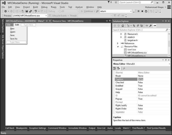
Menus allow you to arrange commands in a logical and easy-to-find fashion. With the Menu editor, you can create and edit menus by working directly with a menu bar that closely resembles the one in your finished application. To create a menu, follow the steps given below −
Step 1 − Right-click on your project and select Add → Resources. You will see the Add Resources dialog box.
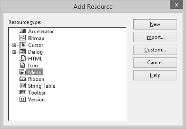
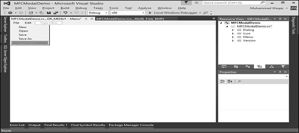
Step 2 − Select Menu and click New. You will see the rectangle that contains "Type Here" on the menu bar.
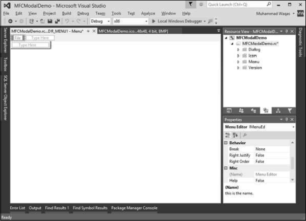
Step 3 − Write some menu options like File, Edit, etc. as shown in the following snapshot.
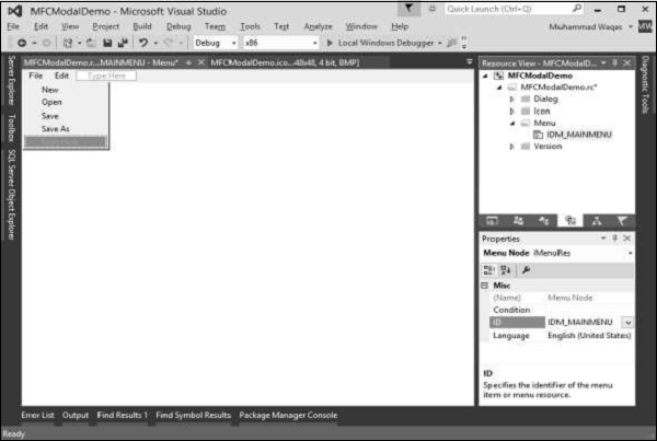
Step 4 − If you expand the Menu folder in Resource View, you will see the Menu identifier IDR_MENU1. Right-click on this identifier and change it to IDM_MAINMENU.
Step 5 − Save all the changes.
Step 6 − We need to attach this menu to our dialog box. Expand your Dialog folder in Solution Explorer and double click on the dialog box identifier.
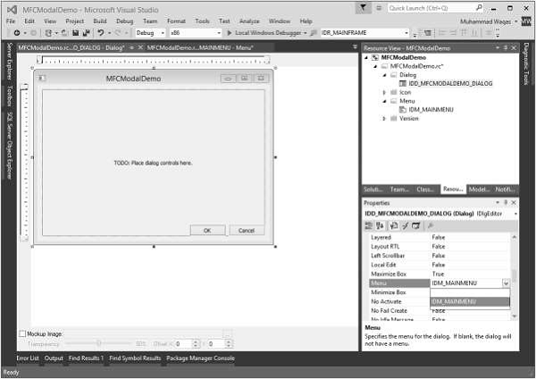
Step 7 − You will see the menu field in the Properties. Select the Menu identifier from the dropdown as shown above.
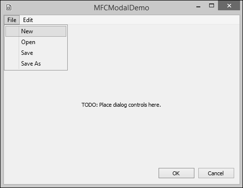
Step 8 − Run this application and you will see the following dialog box which also contains menu options.
A toolbar is a Windows control that allows the user to perform some actions on a form by clicking a button instead of using a menu.
To create a toolbar, following are the steps.
Step 1 − Right-click on your project and select Add → Resources. You will see the Add Resources dialog box.
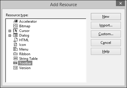
Step 2 − Select Toolbar and click New. You will see the following screen.
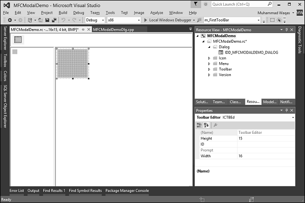
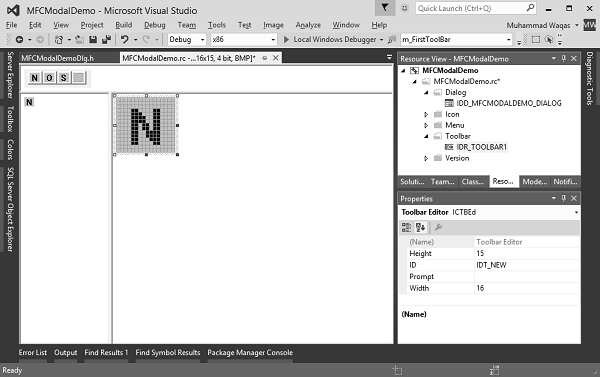
Step 3 − Design your toolbar in the designer as shown in the following screenshot and specify the IDs as well.
Step 4 − Add these two variables in CMFCModalDemoDlg class.
CToolBar m_wndToolBar; BOOL butD;
Step 5 − Following is the complete implementation of CMFCModalDemoDlg in CMFCModalDemoDlg.h file −
class CMFCModalDemoDlg : public CDialogEx < // Construction public: CMFCModalDemoDlg(CWnd* pParent = NULL); // standard constructor // Dialog Data #ifdef AFX_DESIGN_TIME enum < IDD = IDD_MFCMODALDEMO_DIALOG >; #endif protected: virtual void DoDataExchange(CDataExchange* pDX); // DDX/DDV support // Implementation protected: HICON m_hIcon; CToolBar m_wndToolBar; BOOL butD; // Generated message map functions virtual BOOL OnInitDialog(); afx_msg void OnPaint(); afx_msg HCURSOR OnQueryDragIcon(); DECLARE_MESSAGE_MAP() public: afx_msg void OnBnClickedOk(); >;
Step 6 − Update CMFCModalDemoDlg::OnInitDialog() as shown in the following code.
BOOL CMFCModalDemoDlg::OnInitDialog() < CDialogEx::OnInitDialog(); // Set the icon for this dialog. The framework does this automatically // when the application's main window is not a dialog SetIcon(m_hIcon, TRUE); // Set big icon SetIcon(m_hIcon, FALSE); // Set small icon if (!m_wndToolBar.Create(this) || !m_wndToolBar.LoadToolBar(IDR_TOOLBAR1)) //if (!m_wndToolBar.CreateEx(this, TBSTYLE_FLAT, WS_CHILD | // WS_VISIBLE | CBRS_TOP | CBRS_GRIPPER | CBRS_TOOLTIPS | // CBRS_FLYBY | CBRS_SIZE_DYNAMIC) || // !m_wndToolBar.LoadToolBar(IDR_TOOLBAR1)) < TRACE0("Failed to Create Dialog Toolbar\n"); EndDialog(IDCANCEL); >butD = TRUE; CRect rcClientOld; // Old Client Rect CRect rcClientNew; // New Client Rect with Tollbar Added // Retrive the Old Client WindowSize // Called to reposition and resize control bars in the client area of a window // The reposQuery FLAG does not really traw the Toolbar. It only does the calculations. // And puts the new ClientRect values in rcClientNew so we can do the rest of the Math. GetClientRect(rcClientOld); RepositionBars(AFX_IDW_CONTROLBAR_FIRST, AFX_IDW_CONTROLBAR_LAST, 0, reposQuery, rcClientNew); // All of the Child Windows (Controls) now need to be moved so the Tollbar does not cover them up. // Offest to move all child controls after adding Tollbar CPoint ptOffset(rcClientNew.left - rcClientOld.left, rcClientNew.top - rcClientOld.top); CRect rcChild; CWnd* pwndChild = GetWindow(GW_CHILD); //Handle to the Dialog Controls while (pwndChild) // Cycle through all child controls < pwndChild ->GetWindowRect(rcChild); // Get the child control RECT ScreenToClient(rcChild); // Changes the Child Rect by the values of the claculated offset rcChild.OffsetRect(ptOffset); pwndChild -> MoveWindow(rcChild, FALSE); // Move the Child Control pwndChild = pwndChild -> GetNextWindow(); > CRect rcWindow; // Get the RECT of the Dialog GetWindowRect(rcWindow); // Increase width to new Client Width rcWindow.right += rcClientOld.Width() - rcClientNew.Width(); // Increase height to new Client Height rcWindow.bottom += rcClientOld.Height() - rcClientNew.Height(); // Redraw Window MoveWindow(rcWindow, FALSE); // Now we REALLY Redraw the Toolbar RepositionBars(AFX_IDW_CONTROLBAR_FIRST, AFX_IDW_CONTROLBAR_LAST, 0); // TODO: Add extra initialization here return TRUE; // return TRUE unless you set the focus to a control >
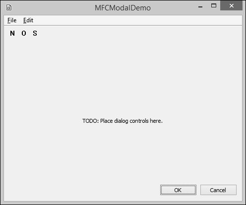
Step 7 − Run this application. You will see the following dialog box which also contains the toolbar.
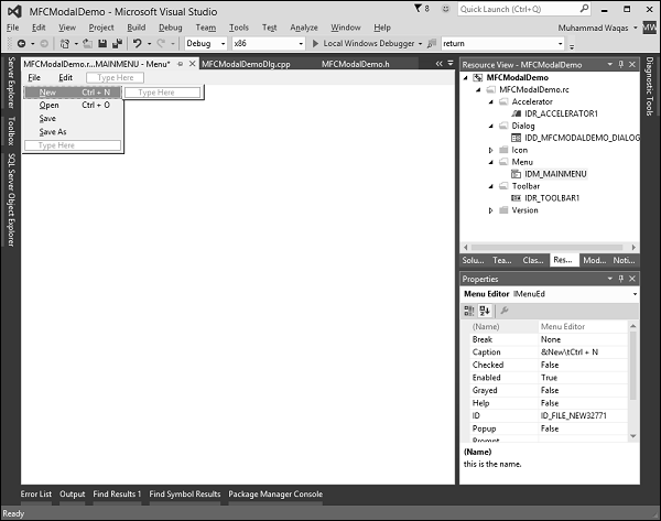
An access key is a letter that allows the user to perform a menu action faster by using the keyboard instead of the mouse. This is usually faster because the user would not need to position the mouse anywhere, which reduces the time it takes to perform the action.
Step 1 − To create an access key, type an ampersand "&" on the left of the menu item.
Step 2 − Repeat this step for all menu options. Run this application and press Alt. You will see that the first letter of all menu options are underlined.
A shortcut key is a key or a combination of keys used by advanced users to perform an action that would otherwise be done on a menu item. Most shortcuts are a combination of the Ctrl key simultaneously pressed with a letter key. For example, Ctrl + N, Ctrl + O, or Ctrl + D.
To create a shortcut, on the right side of the string that makes up a menu caption, rightclick on the menu item and select properties.
In the Caption field type \t followed by the desired combination as shown below for the New menu option. Repeat the step for all menu options.
An Accelerator Table is a list of items where each item of the table combines an identifier, a shortcut key, and a constant number that specifies the kind of accelerator key. Just like the other resources, an accelerator table can be created manually in a .rc file. Following are the steps to create an accelerator table.
Step 1 − To create an accelerator table, right-click on *.rc file in the solution explorer.
Step 2 − Select Accelerator and click New.
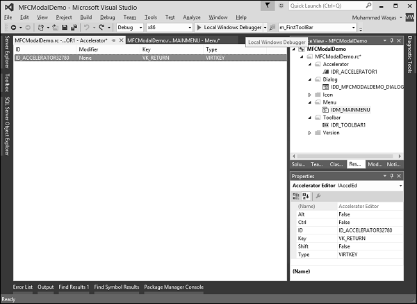
Step 3 − Click the arrow of the ID combo box and select menu Items.
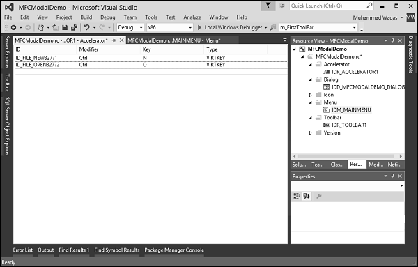
Step 4 − Select Ctrl from the Modifier dropdown.
Step 5 − Click the Key box and type the respective Keys for both menu options.
We will also add New menu item event handler to testing. Right-click on the New menu option.
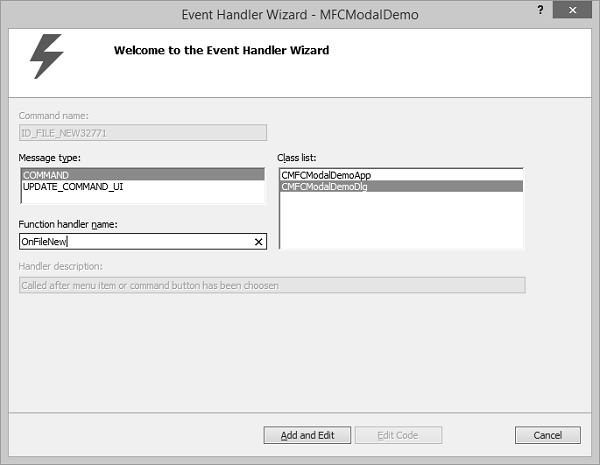
Step 6 − You can specify a class, message type and handler name. For now, let us leave it as it is and click Add and Edit button.
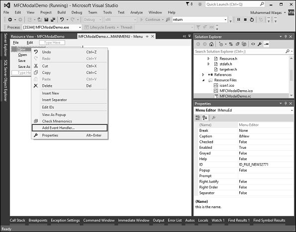
Step 7 − Select Add Event Handler.
Step 8 − You will now see the event added at the end of the CMFCModalDemoDlg.cpp file.
void CMFCModalDemoDlg::OnFileNew() < // TODO: Add your command handler code here MessageBox(L"File >New menu option"); >
Step 9 − Now Let us add a message box that will display the simple menu option message.
To start accelerator table in working add the HACCEL variable and ProcessMessageFilter as shown in the following CMFCModalDemoApp.
class CMFCModalDemoApp : public CWinApp < public: CMFCModalDemoApp(); // Overrides public: virtual BOOL InitInstance(); HACCEL m_hAccelTable; // Implementation DECLARE_MESSAGE_MAP() virtual BOOL ProcessMessageFilter(int code, LPMSG lpMsg); >;
Step 10 − Load Accelerator and the following call in the CMFCModalDemoApp::InitInstance().
m_hAccelTable = LoadAccelerators(AfxGetInstanceHandle(), MAKEINTRESOURCE(IDR_ACCELERATOR1));
Step 11 − Here is the implementation of ProcessMessageFilter.
BOOL CMFCModalDemoApp::ProcessMessageFilter(int code, LPMSG lpMsg) < if (code >= 0 && m_pMainWnd && m_hAccelTable) < if (::TranslateAccelerator(m_pMainWnd ->m_hWnd, m_hAccelTable, lpMsg)) return TRUE; > return CWinApp::ProcessMessageFilter(code, lpMsg); >
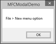
Step 12 − When the above code is compiled and executed, you will see the following output.
Step 13 − Press Alt button followed by F key and then N key or Ctrl + N. You will see the following message.
A property sheet, also known as a tab dialog box, is a dialog box that contains property pages. Each property page is based on a dialog template resource and contains controls. It is enclosed on a page with a tab on top. The tab names the page and indicates its purpose. Users click a tab in the property sheet to select a set of controls.
To create property pages, let us look into a simple example by creating a dialog based MFC project.
Once the project is created, we need to add some property pages.
Visual Studio makes it easy to create resources for property pages by displaying the Add Resource dialog box, expanding the Dialog node and selecting one of the IDD_PROPPAGE_X items.
Step 1 − Right-click on your project in solution explorer and select Add → Resources.
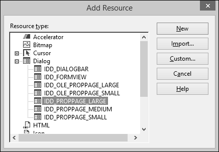
Step 2 − Select the IDD_PROPPAGE_LARGE and click NEW.
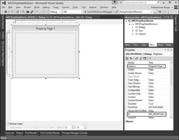
Step 3 − Let us change ID and Caption of this property page to IDD_PROPPAGE_1 and Property Page 1 respectively as shown above.
Step 4 − Right-click on the property page in designer window.
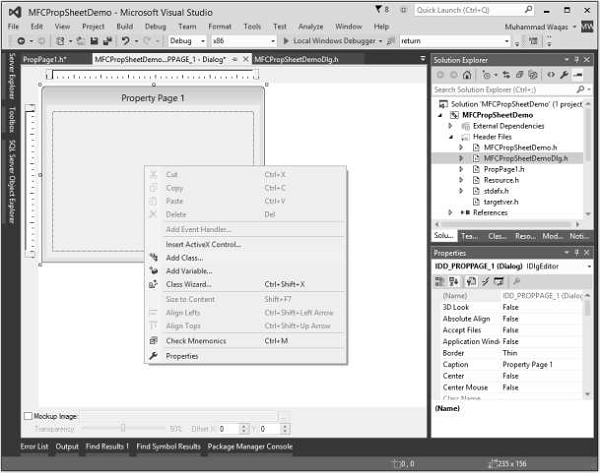
Step 5 − Select the Add Class option.

Step 6 − Enter the class name and select CPropertyPage from base class dropdown list.
Step 7 − Click Finish to continue.
Step 8 − Add one more property page with ID IDD_PROPPAGE_2 and Caption Property Page 2 by following the above mentioned steps.
Step 9 − You can now see two property pages created. To implement its functionality, we need a property sheet.
The Property Sheet groups the property pages together and keeps it as entity.
To create a property sheet, follow the steps given below −
Step 1 − Right-click on your project and select Add > Class menu options.
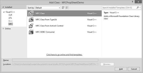
Step 2 − Select Visual C++ → MFC from the left pane and MFC Class in the template pane and click Add.
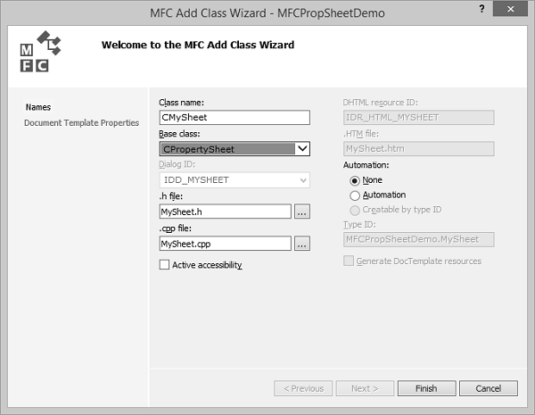
Step 3 − Enter the class name and select CPropertySheet from base class dropdown list.
Step 4 − Click finish to continue.
Step 5 − To launch this property sheet, we need the following changes in our main project class.
Step 6 − Add the following references in CMFCPropSheetDemo.cpp file.
#include "MySheet.h" #include "PropPage1.h" #include "PropPage2.h"
Step 7 − Modify the CMFCPropSheetDemoApp::InitInstance() method as shown in the following code.
CMySheet mySheet(L"Property Sheet Demo"); CPropPage1 page1; CPropPage2 page2; mySheet.AddPage(&page1); mySheet.AddPage(&page2); m_pMainWnd = &mySheet; INT_PTR nResponse = mySheet.DoModal();
Step 8 − Here is the complete implementation of CMFCPropSheetDemo.cpp file.
// MFCPropSheetDemo.cpp : Defines the class behaviors for the application. // #include "stdafx.h" #include "MFCPropSheetDemo.h" #include "MFCPropSheetDemoDlg.h" #include "MySheet.h" #include "PropPage1.h" #include "PropPage2.h" #ifdef _DEBUG #define new DEBUG_NEW #endif // CMFCPropSheetDemoApp BEGIN_MESSAGE_MAP(CMFCPropSheetDemoApp, CWinApp) ON_COMMAND(ID_HELP, &CWinApp::OnHelp) END_MESSAGE_MAP() // CMFCPropSheetDemoApp construction CMFCPropSheetDemoApp::CMFCPropSheetDemoApp() < // support Restart Manager m_dwRestartManagerSupportFlags = AFX_RESTART_MANAGER_SUPPORT_RESTART; // TODO: add construction code here, // Place all significant initialization in InitInstance >// The one and only CMFCPropSheetDemoApp object CMFCPropSheetDemoApp theApp; // CMFCPropSheetDemoApp initialization BOOL CMFCPropSheetDemoApp::InitInstance() < // InitCommonControlsEx() is required on Windows XP if an application // manifest specifies use of ComCtl32.dll version 6 or later to enable // visual styles. Otherwise, any window creation will fail. INITCOMMONCONTROLSEX InitCtrls; InitCtrls.dwSize = sizeof(InitCtrls); // Set this to include all the common control classes you want to use // in your application. InitCtrls.dwICC = ICC_WIN95_CLASSES; InitCommonControlsEx(&InitCtrls); CWinApp::InitInstance(); AfxEnableControlContainer(); // Create the shell manager, in case the dialog contains // any shell tree view or shell list view controls. CShellManager *pShellManager = new CShellManager; // Activate "Windows Native" visual manager for enabling themes in MFC controls CMFCVisualManager::SetDefaultManager(RUNTIME_CLASS(CMFCVisualManagerWindows)); // Standard initialization // If you are not using these features and wish to reduce the size // of your final executable, you should remove from the following // the specific initialization routines you do not need // Change the registry key under which our settings are stored // TODO: You should modify this string to be something appropriate // such as the name of your company or organization SetRegistryKey(_T("Local AppWizard-Generated Applications")); CMySheet mySheet(L"Property Sheet Demo"); CPropPage1 page1; CPropPage2 page2; mySheet.AddPage(&page1); mySheet.AddPage(&page2); m_pMainWnd = &mySheet; INT_PTR nResponse = mySheet.DoModal(); if (nResponse == IDOK) < // TODO: Place code here to handle when the dialog is // dismissed with OK >else if (nResponse == IDCANCEL) < // TODO: Place code here to handle when the dialog is // dismissed with Cancel >else if (nResponse == -1) < TRACE(traceAppMsg, 0, "Warning: dialog creation failed, so application is terminating unexpectedly.\n"); TRACE(traceAppMsg, 0, "Warning: if you are using MFC controls on the dialog, you cannot #define _AFX_NO_MFC_CONTROLS_IN_DIALOGS.\n"); >// Delete the shell manager created above. if (pShellManager != NULL) < delete pShellManager; >// Since the dialog has been closed, return FALSE so that we exit the // application, rather than start the application's message pump. return FALSE; >
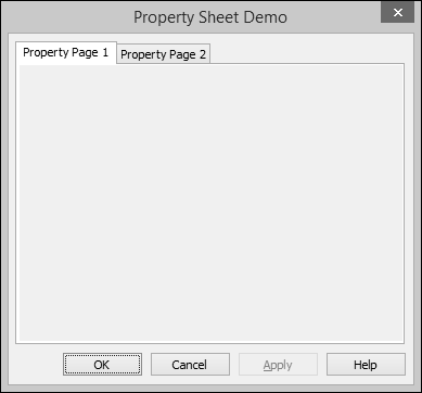
Step 9 − When the above code is compiled and executed, you will see the following dialog box. This dialog box contains two property pages.
Layout of controls is very important and critical for application usability. It is used to arrange a group of GUI elements in your application. There are certain important things to consider while selecting layout −
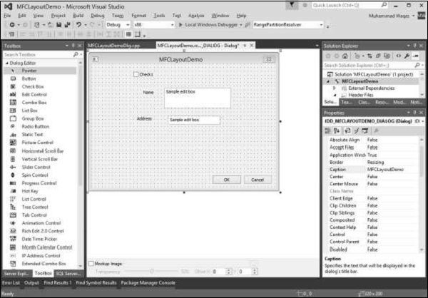
Let us create new Dialog based MFC Project MFCLayoutDemo.
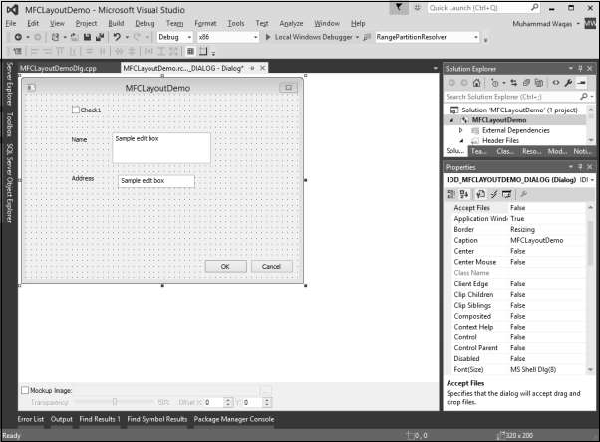
Step 1 − Once the project is created, you will see the following screen.
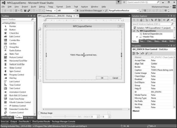
Step 2 − Delete the TODO from the dialog box.
Step 3 − Drag some controls from the Toolbox which you can see on the left side.
(We will drag one Static Text and one Edit Control as shown in the following snapshot).
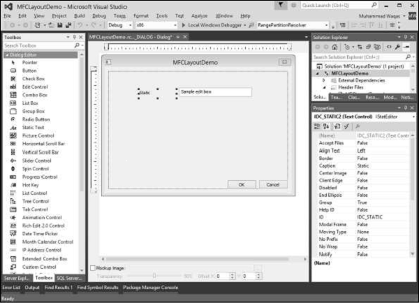
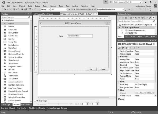
Step 4 − Change the Caption of the Static Text to Name.
Control grid is the guiding grid dots, which can help in positioning of the controls you are adding at the time of designing.
To enable the control grid, you need to click the Toggle Grid button in the toolbar as shown in the following snapshot.
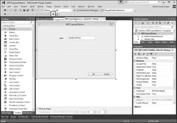
After you have added a control to a dialog box, it assumes either its default size or the size you drew it with. To help with the sizes of controls on the form or dialog box, Visual Studio provides a visual grid made of black points.
To resize a control, that is, to give it a particular width or height, position the mouse on one of the handles and drag it in the desired direction.
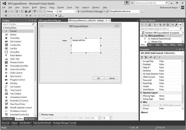
You can now resize the controls with the help of this dotted grid.
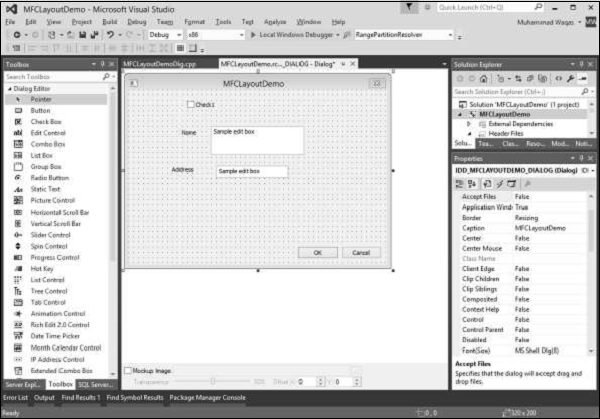
The controls you position on a dialog box or a form assume their given place. Most of the time, these positions are not practical. You can move them around to any position of your choice.
Let us add some more controls −
Step 1 − To move a control, click and drag it in the desired direction until it reaches the intended position.
Step 2 − To move a group of controls, first select them. Then drag the selection to the desired location. Let us select the Static Texts and Edit Controls.

Step 3 − Move these selected controls to the left side.

To help with positioning the controls, Visual Studio provides the Dialog toolbar with the following buttons.
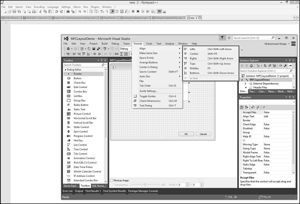
Step 1 − Let us align the Check box and Static Text controls to the left by selecting all these controls.
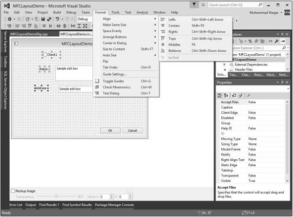
Step 2 − Select the Format → Align → Lefts.
Step 3 − You can now see all these controls are aligned to the left.
The controls you add to a form or a dialog box are positioned in a sequence that follows the order they were added. When you add control(s) regardless of the section or area you place the new control, it is sequentially positioned at the end of the existing controls. If you do not fix it, the user would have a hard time navigating the controls. The sequence of controls navigation is also known as the tab order.
To change the tab, you can either use the Format → Tab Order menu option or you can also use the Ctrl + D shortcut. Let us press Ctrl + D.
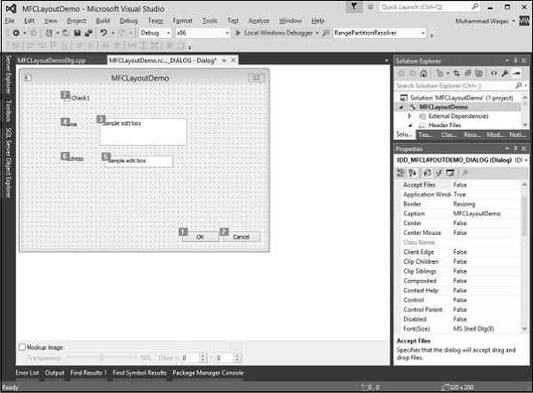
You can now see the order in which all these controls are added to this dialog box. To Change the order or sequence of controls, click on all the controls in sequence in which you want to navigate.
In this example, we will first click on the checkbox followed by Name and Address Edit controls. Then click OK and Cancel as shown in the following snapshot.

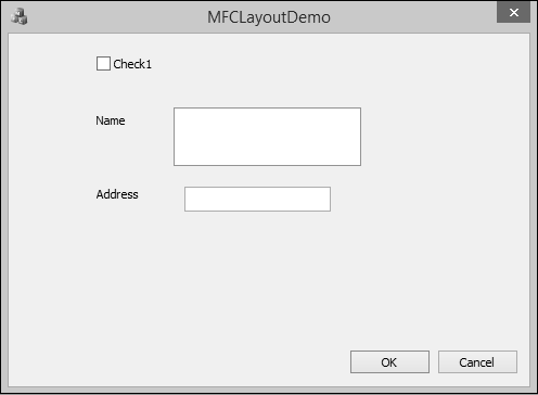
Let us run this application and you will see the following output.
In MFC applications, after visually adding a control to your application, if you want to refer to it in your code, you can declare a variable based on, or associated with that control. The MFC library allows you to declare two types of variables for some of the controls used in an application a value or a control variable.
A control variable is a variable based on the class that manages the control. For example, a button control is based on the CButton class.
To see these concepts in real programming, let us create an MFC dialog based project MFCControlManagement.
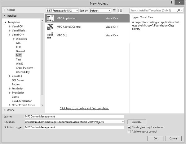
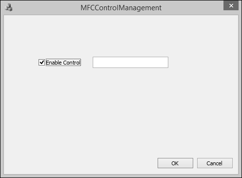
Once the project is created, you will see the following dialog box in designer window.
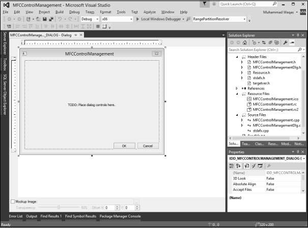
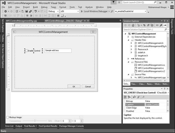
Step 1 − Delete the TODO line and drag one checkbox and one Edit control as shown in the following snapshot. Change the caption of checkbox to Enable Control.
Step 2 − Right-click on the checkbox.
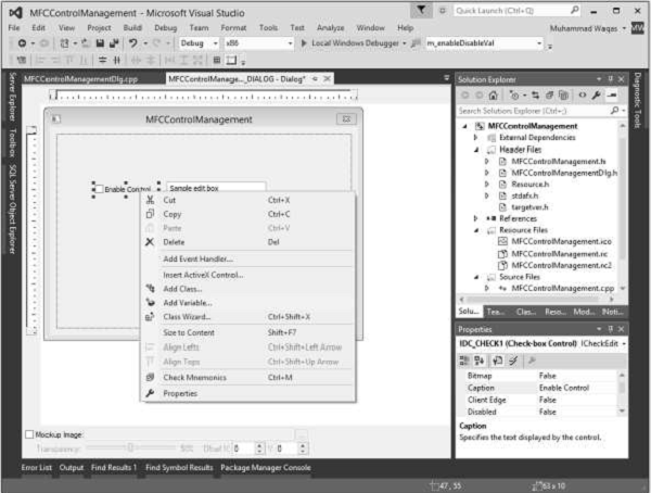
Step 3 − Select Add Variable.
Step 4 − You can now see the Add Member Variable Wizard.
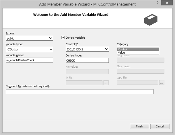
You can select different options on this dialog box. For checkbox, the variable type is CButton. It is selected by default in this dialog box.
Similarly, the control ID is also selected by default now we need to select Control in the Category combo box, and type m_enableDisableCheck in the Variable Name edit box and click finish.
Step 5 − Similarly, add Control Variable of Edit control with the settings as shown in the following snapshot.

Observe the header file of the dialog class. You can see that the new variables have been added now.
CButton m_enableDisableCheck; CEdit m_myEditControl;
Another type of variable you can declare for a control is the value variable. Not all controls provide a value variable.
Let us look into this type of variable for checkbox and edit control.
Step 1 − Right-click on the checkbox and select Add Variable.

Step 2 − The Variable type is BOOL. Select Value from the Category dropdown list.
Step 3 − Click Finish to continue.
Step 4 − Similarly, add value Variable for Edit control with the settings as shown in the following snapshot.
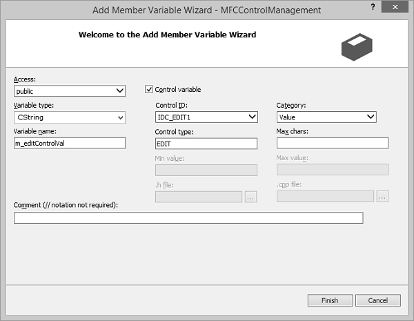
Step 5 − Type CString in variable type and m_editControlVal in the variable name field.
Step 6 − You can now see these variables added in the Header file.
bool m_enableDisableVal; CString m_editControlVal;
After adding a control to your application, whether you visually added it or created it dynamically, you will also decide how to handle the possible actions that the user can perform on the control.
Let us look into the same example in which we added event handler for checkbox.
Step 1 − Right-click the control for which you want to handle the notification event.
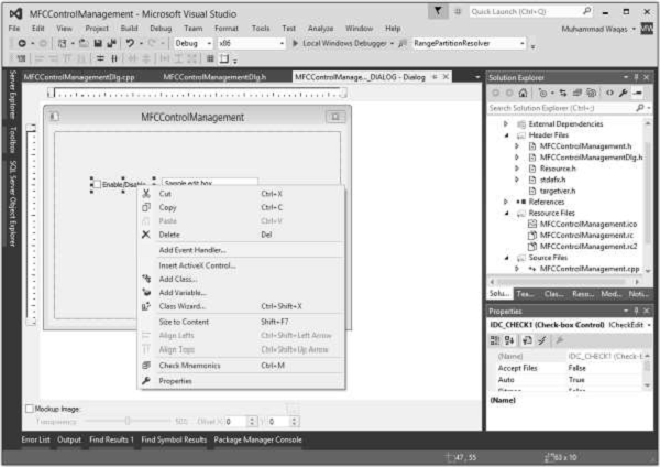
Step 2 − On the shortcut menu, click Add Event Handler to display the Event Handler Wizard.
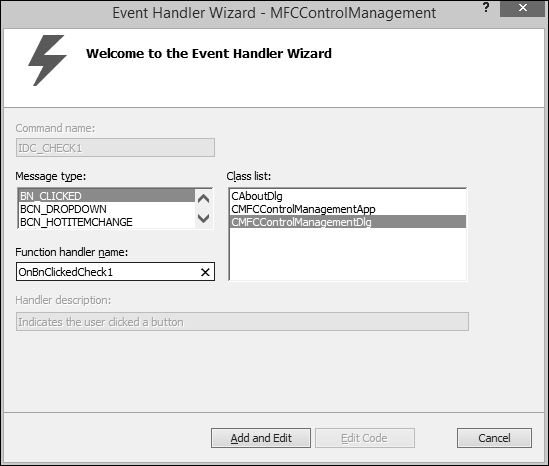
Step 3 − Select the event in the Message type box to add to the class selected in the Class list box.
Step 4 − Accept the default name in the Function handler name box, or provide the name of your choice.
Step 5 − Click Add and edit to add the event handler.
Step 6 − You can now see the following event added at the end of CMFCControlManagementDlg.cpp file.
void CMFCControlManagementDlg::OnBnClickedCheck1() < // TODO: Add your control notification handler code here >
So far, we have seen how to add controls to an application. We will now see how to manage these controls as per user requirement. We can use the control variable/instance in a particular event handler.
Step 1 − Let us look into the following example. Here, we will enable/disable the edit control when the checkbox is checked/unchecked.
Step 2 − We have now added the checkbox click event handler. Here is the implementation −
void CMFCControlManagementDlg::OnBnClickedCheck1() < // TODO: Add your control notification handler code here UpdateData(TRUE); if (m_enableDisableVal) m_myEditControl.EnableWindow(TRUE); else m_myEditControl.EnableWindow(FALSE); >
Step 3 − When the dialog is created, we need to add the following code to CMFCControlManagementDlg::OnInitDialog(). This will manage these controls.
UpdateData(TRUE); if (m_enableDisableVal) m_myEditControl.EnableWindow(TRUE); else m_myEditControl.EnableWindow(FALSE);
Step 4 − Here is the complete implementation of CMFCControlManagementDlg.cpp file.
// MFCControlManagementDlg.cpp : implementation file // #include "stdafx.h" #include "MFCControlManagement.h" #include "MFCControlManagementDlg.h" #include "afxdialogex.h" #ifdef _DEBUG #define new DEBUG_NEW #endif // CAboutDlg dialog used for App About class CAboutDlg : public CDialogEx < public: CAboutDlg(); // Dialog Data #ifdef AFX_DESIGN_TIME enum < IDD = IDD_ABOUTBOX >; #endif protected: virtual void DoDataExchange(CDataExchange* pDX); // DDX/DDV support // Implementation protected: DECLARE_MESSAGE_MAP() >; CAboutDlg::CAboutDlg() : CDialogEx(IDD_ABOUTBOX) < >void CAboutDlg::DoDataExchange(CDataExchange* pDX) < CDialogEx::DoDataExchange(pDX); >BEGIN_MESSAGE_MAP(CAboutDlg, CDialogEx) END_MESSAGE_MAP() // CMFCControlManagementDlg dialog CMFCControlManagementDlg::CMFCControlManagementDlg(CWnd* pParent /* = NULL*/) :CDialogEx(IDD_MFCCONTROLMANAGEMENT_DIALOG, pParent) , m_enableDisableVal(FALSE) , m_editControlVal(_T("")) < m_hIcon = AfxGetApp()&rarr LoadIcon(IDR_MAINFRAME); >void CMFCControlManagementDlg::DoDataExchange(CDataExchange* pDX) < CDialogEx::DoDataExchange(pDX); DDX_Control(pDX, IDC_CHECK1, m_enableDisableCheck); DDX_Control(pDX, IDC_EDIT1, m_myEditControl); DDX_Check(pDX, IDC_CHECK1, m_enableDisableVal); DDX_Text(pDX, IDC_EDIT1, m_editControlVal); >BEGIN_MESSAGE_MAP(CMFCControlManagementDlg, CDialogEx) ON_WM_SYSCOMMAND() ON_WM_PAINT() ON_WM_QUERYDRAGICON() ON_BN_CLICKED(IDC_CHECK1, &CMFCControlManagementDlg::OnBnClickedCheck1) END_MESSAGE_MAP() // CMFCControlManagementDlg message handlers BOOL CMFCControlManagementDlg::OnInitDialog() < CDialogEx::OnInitDialog(); // Add "About. " menu item to system menu. // IDM_ABOUTBOX must be in the system command range. ASSERT((IDM_ABOUTBOX & 0xFFF0) == IDM_ABOUTBOX); ASSERT(IDM_ABOUTBOX < 0xF000); CMenu* pSysMenu = GetSystemMenu(FALSE); if (pSysMenu != NULL) < BOOL bNameValid; CString strAboutMenu; bNameValid = strAboutMenu.LoadString(IDS_ABOUTBOX); ASSERT(bNameValid); if (!strAboutMenu.IsEmpty()) < pSysMenu → AppendMenu(MF_SEPARATOR); pSysMenu → AppendMenu(MF_STRING, IDM_ABOUTBOX, strAboutMenu); >> // Set the icon for this dialog. The framework does this automatically // when the application's main window is not a dialog SetIcon(m_hIcon, TRUE); // Set big icon SetIcon(m_hIcon, FALSE); // Set small icon // TODO: Add extra initialization here UpdateData(TRUE); if (m_enableDisableVal) m_myEditControl.EnableWindow(TRUE); else m_myEditControl.EnableWindow(FALSE); return TRUE; // return TRUE unless you set the focus to a control > void CMFCControlManagementDlg::OnSysCommand(UINT nID, LPARAM lParam) < if ((nID & 0xFFF0) == IDM_ABOUTBOX) < CAboutDlg dlgAbout; dlgAbout.DoModal(); >else < CDialogEx::OnSysCommand(nID, lParam); >> // If you add a minimize button to your dialog, you will need the code below // to draw the icon. For MFC applications using the document/view model, // this is automatically done for you by the framework. void CMFCControlManagementDlg::OnPaint() < if (IsIconic()) < CPaintDC dc(this); // device context for painting SendMessage(WM_ICONERASEBKGND, reinterpret_cast(dc.GetSafeHdc()), 0); // Center icon in client rectangle int cxIcon = GetSystemMetrics(SM_CXICON); int cyIcon = GetSystemMetrics(SM_CYICON); CRect rect; GetClientRect(&rect); int x = (rect.Width() - cxIcon + 1) / 2; int y = (rect.Height() - cyIcon + 1) / 2; // Draw the icon dc.DrawIcon(x, y, m_hIcon); >else < CDialogEx::OnPaint(); >> // The system calls this function to obtain the cursor to display while the user drags // the minimized window. HCURSOR CMFCControlManagementDlg::OnQueryDragIcon() < return static_cast(m_hIcon); > void CMFCControlManagementDlg::OnBnClickedCheck1() < // TODO: Add your control notification handler code here UpdateData(TRUE); if (m_enableDisableVal) m_myEditControl.EnableWindow(TRUE); else m_myEditControl.EnableWindow(FALSE); >
Step 5 − When the above code is compiled and executed, you will see the following output. The checkbox is unchecked by default. This disables the edit control too.
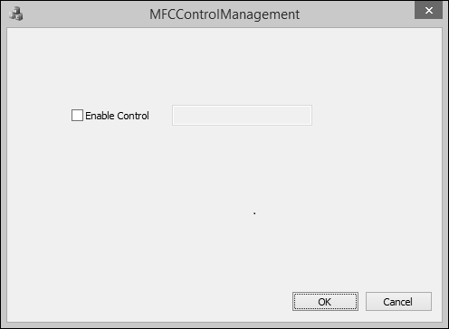
Step 6 − Check the Enable Control checkbox. This will automatically enable the edit control.
Windows controls are objects that users can interact with to enter or manipulate data. They commonly appear in dialog boxes or on toolbars. There are various types of controls −
| Sr.No. | Controls & Description |
|---|---|
| 1 | Static Control |
A static control is an object that displays information to the user without his or her direct intervention. It can be used to show colors, a geometric shape, or a picture such as an icon, a bitmap, or an animation.
An animation control is a window that displays an Audio clip in AVI format. An AVI clip is a series of bitmap frames, like a movie. Animation controls can only play simple AVI clips, and they do not support sound. It is represented by the CAnimateCtrl class.
A button is an object that the user clicks to initiate an action. Button control is represented by CButton class.
A bitmap button displays a picture or a picture and text on its face. This is usually intended to make the button a little explicit. A bitmap button is created using the CBitmapButton class, which is derived from CButton.
A command button is an enhanced version of the regular button. It displays a green arrow icon on the left, followed by a caption in regular size. Under the main caption, it can display another smaller caption that serves as a hint to provide more information.
A static control displays a text string, box, rectangle, icon, cursor, bitmap, or enhanced metafile. It is represented by CStatic class. It can be used to label, box, or separateother controls. A static control normally takes no input and provides no output.
A list box displays a list of items, such as filenames, that the user can view and select. A List box is represented by CListBox class. In a single-selection list box, the user can select only one item. In a multiple-selection list box, a range of items can be selected. When the user selects an item, it is highlighted and the list box sends a notification message to the parent window.
A combo box consists of a list box combined with either a static control or edit control. it is represented by CComboBox class. The list-box portion of the control may be displayed at all times or may only drop down when the user selects the drop-down arrow next to the control.
A radio button is a control that appears as a dot surrounded by a round box. In reality, a radio button is accompanied by one or more other radio buttons that appear and behave as a group.
A checkbox is a Windows control that allows the user to set or change the value of an item as true or false.
An Image List is a collection of same-sized images, each of which can be referred to by its zero-based index. Image lists are used to efficiently manage large sets of icons or bitmaps. Image lists are represented by CImageList class.
An Edit Box is a rectangular child window in which the user can enter text. It is represented by CEdit class.
A Rich Edit Control is a window in which the user can enter and edit text. The text can be assigned character and paragraph formatting, and can include embedded OLE objects. It is represented by CRichEditCtrl class.
A group box is a static control used to set a visible or programmatic group of controls. The control is a rectangle that groups other controls together.
A Spin Button Control (also known as an up-down control) is a pair of arrow buttons that the user can click to increment or decrement a value, such as a scroll position or a number displayed in a companion control. it is represented by CSpinButtonCtrl class.
It manages the Updown Controls.
A progress bar control is a window that an application can use to indicate the progress of a lengthy operation. It consists of a rectangle that is gradually filled, from left to right, with the system highlight color as an operation progresses. It is represented by CProgressCtrl class.
A progress bars is a window that an application can use to indicate the progress of a operation.
A timer is a non-spatial object that uses recurring lapses of time from a computer or fromyour application. To work, every lapse of period, the control sends a message to the operating system. Unlike most other controls, the MFC timer has neither a button to represent it nor a class. To create a timer, you simply call the CWnd::SetTimer() method. This function call creates a timer for your application. Like the other controls, a timer uses an identifier.
The date and time picker control (CDateTimeCtrl) implements an intuitive and recognizable method of entering or selecting a specific date. The main interface of the control is similar in functionality to a combo box. However, if the user expands the control, a month calendar control appears (by default), allowing the user to specify a particular date. When a date is chosen, the month calendar control automatically disappears.
If you need to display a picture for your application, Visual C++ provides a special control for that purpose.
The Image editor has an extensive set of tools for creating and editing images, as wellas features to help you create toolbar bitmaps. In addition to bitmaps, icons, and cursors, you can edit images in GIF or JPEG format using commands on the Image menu and tools on the Image Editor Toolbar.
A Slider Control (also known as a trackbar) is a window containing a slider and optional tick marks. When the user moves the slider, using either the mouse or the direction keys, the control sends notification messages to indicate the change. There are two types of sliders − horizontal and vertical. It is represented by CSliderCtrl class.
A scrollbar is a graphical control element with which continuous text, pictures or anything else can be scrolled in two directions along a control by clicking an arrow. This control can assume one of two directions − horizontal or vertical. It is represented by CScrollBar class.
A Tree View Control is a window that displays a hierarchical list of items, such as the headings in a document, the entries in an index, or the files and directories on a disk. Each item consists of a label and an optional bitmapped image, and each item can have a list of subitems associated with it. By clicking an item, the user can expand and collapse the associated list of subitems. It is represented by CTreeCtrl class.
Encapsulates the functionality of a List View Control, which displays a collection of items each consisting of an icon (from an image list) and a label. It is represented by CListCtrl class. A list control consists of using one of four views to display a list of items.
An application is made of various objects. Most of the time, more than one application is running on the computer and the operating system is constantly asked to perform some assignments. Because there can be so many requests presented unpredictably, the operating system leaves it up to the objects to specify what they want, when they want it, and what behavior or result they expect.
Since Windows is a message-oriented operating system, a large portion of programming for the Windows environment involves message handling. Each time an event such as a keystroke or mouse click occurs, a message is sent to the application, which must then handle the event.
class CMainFrame : public CFrameWnd < public: CMainFrame(); protected: DECLARE_MESSAGE_MAP() >;
#include class CMainFrame : public CFrameWnd < public: CMainFrame(); protected: DECLARE_MESSAGE_MAP() >; CMainFrame::CMainFrame() < // Create the window's frame Create(NULL, L"MFC Messages Demo", WS_OVERLAPPEDWINDOW, CRect(120, 100, 700, 480), NULL); >class CMessagesApp : public CWinApp < public: BOOL InitInstance(); >; BEGIN_MESSAGE_MAP(CMainFrame, CFrameWnd) END_MESSAGE_MAP() BOOL CMessagesApp::InitInstance()< m_pMainWnd = new CMainFrame; m_pMainWnd->ShowWindow(SW_SHOW); m_pMainWnd->UpdateWindow(); return TRUE; > CMessagesApp theApp;
Let us look into a simple example by creating a new Win32 project.
Step 1 − To create an MFC project, right-click on the project and select Properties.
Step 2 − In the left section, click Configuration Properties → General.
Step 3 − Select the ‘Use MFC in Shared DLL’ option in Project Defaults section and click OK.
Step 4 − We need to add a new source file.
Step 5 − Right-click on your Project and select Add → New Item.
Step 6 − In the Templates section, click C++ File (.cpp).
Step 7 − Click Add to Continue.
Step 8 − Now, add the following code in the *.cpp file.
#include class CMainFrame : public CFrameWnd < public: CMainFrame(); protected: DECLARE_MESSAGE_MAP() >; CMainFrame::CMainFrame() < // Create the window's frame Create(NULL, L"MFC Messages Demo", WS_OVERLAPPEDWINDOW, CRect(120, 100, 700, 480), NULL); >class CMessagesApp : public CWinApp < public: BOOL InitInstance(); >; BEGIN_MESSAGE_MAP(CMainFrame, CFrameWnd) END_MESSAGE_MAP() BOOL CMessagesApp::InitInstance() < m_pMainWnd = new CMainFrame; m_pMainWnd->ShowWindow(SW_SHOW); m_pMainWnd->UpdateWindow(); return TRUE; > CMessagesApp theApp;
There are different types of Windows messages like creating a window, showing a window etc. Here are some of the commonly used windows messages.
Given below are the different types of Window messages.
| Message | Map entry | Description |
|---|---|---|
| WM_ACTIVATE | ON_WM_ACTIVATE() | The framework calls this member function when a CWnd object is being activated or deactivated. |
| WM_ACTIVATEA PP |
Let us look into a simple example of window creation.
WM_CREATE − When an object, called a window, is created, the frame that creates the objects sends a message identified as ON_WM_CREATE.
Step 1 − To create ON_WM_CREATE, add afx_msg int OnCreate(LPCREATESTRUCT lpCreateStruct); before the DECLARE_MESSAGE_MAP() as shown below.
class CMainFrame : public CFrameWnd < public: CMainFrame(); protected: afx_msg int OnCreate(LPCREATESTRUCT lpCreateStruct); DECLARE_MESSAGE_MAP() >;
Step 2 − Add the ON_WM_CREATE() after the BEGIN_MESSAGE_MAP(CMainFrame, CFrameWnd) and before END_MESSAGE_MAP()
BEGIN_MESSAGE_MAP(CMainFrame, CFrameWnd) ON_WM_CREATE() END_MESSAGE_MAP()
Step 3 − Here is the Implementation of OnCreate()
int CMainFrame::OnCreate(LPCREATESTRUCT lpCreateStruct) < // Call the base class to create the window if (CFrameWnd::OnCreate(lpCreateStruct) == 0) < // If the window was successfully created, let the user know MessageBox(L"The window has been created. "); // Since the window was successfully created, return 0 return 0; >// Otherwise, return -1 return -1; >
Step 4 − Now your *.cpp file will look like as shown in the following code.
#include class CMainFrame : public CFrameWnd < public: CMainFrame(); protected: afx_msg int OnCreate(LPCREATESTRUCT lpCreateStruct); DECLARE_MESSAGE_MAP() >; CMainFrame::CMainFrame() < // Create the window's frame Create(NULL, L"MFC Messages Demo", WS_OVERLAPPEDWINDOW, CRect(120, 100, 700, 480), NULL); >class CMessagesApp : public CWinApp < public: BOOL InitInstance(); >; BEGIN_MESSAGE_MAP(CMainFrame, CFrameWnd) ON_WM_CREATE() END_MESSAGE_MAP() int CMainFrame::OnCreate(LPCREATESTRUCT lpCreateStruct) < // Call the base class to create the window if (CFrameWnd::OnCreate(lpCreateStruct) == 0) < // If the window was successfully created, let the user know MessageBox(L"The window has been created. "); // Since the window was successfully created, return 0 return 0; >// Otherwise, return -1 return -1; > BOOL CMessagesApp::InitInstance() < m_pMainWnd = new CMainFrame; m_pMainWnd ->ShowWindow(SW_SHOW); m_pMainWnd -> UpdateWindow(); return TRUE; > CMessagesApp theApp;
Step 5 − When the above code is compiled and executed, you will see the following output.
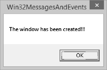
Step 6 − When you click OK, it will display the main window.
One of the main features of a graphical application is to present Windows controls and resources that allow the user to interact with the machine. Examples of controls that we will learn are buttons, list boxes, combo boxes, etc.
One type of resource we introduced in the previous lesson is the menu. Such controls and resources can initiate their own messages when the user clicks them. A message that emanates from a Windows control or a resource is called a command message.
Let us look into a simple example of Command messages.
To provide your application the ability to create a new document, the CWinApp class provides the OnFileNew() method.
afx_msg void OnFileNew(); BEGIN_MESSAGE_MAP(CMainFrame, CFrameWnd) ON_COMMAND(ID_FILE_NEW, CMainFrame::OnFileNew) END_MESSAGE_MAP()
Here is the method definition −
void CMainFrame::OnFileNew() < // Create New file >
A keyboard is a hardware object attached to the computer. By default, it is used to enter recognizable symbols, letters, and other characters on a control. Each key on the keyboard displays a symbol, a letter, or a combination of those, to give an indication of what the key could be used for. The user typically presses a key, which sends a signal to a program.
Each key has a code that the operating system can recognize. This code is known as the virtual key code.
The virtual key codes are as follows.